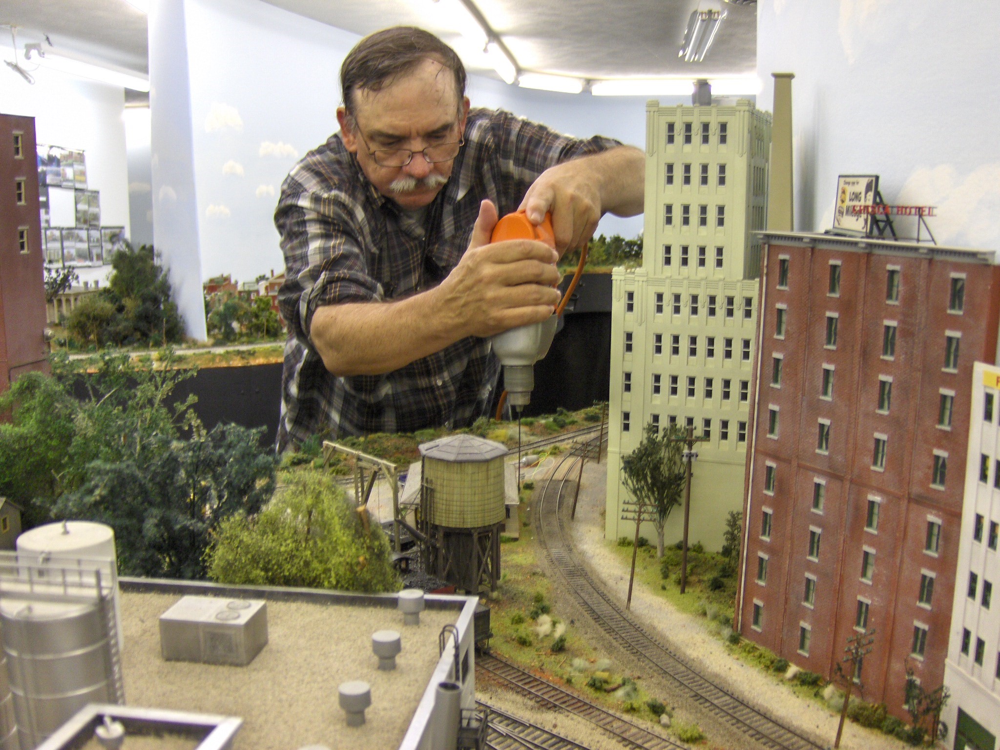
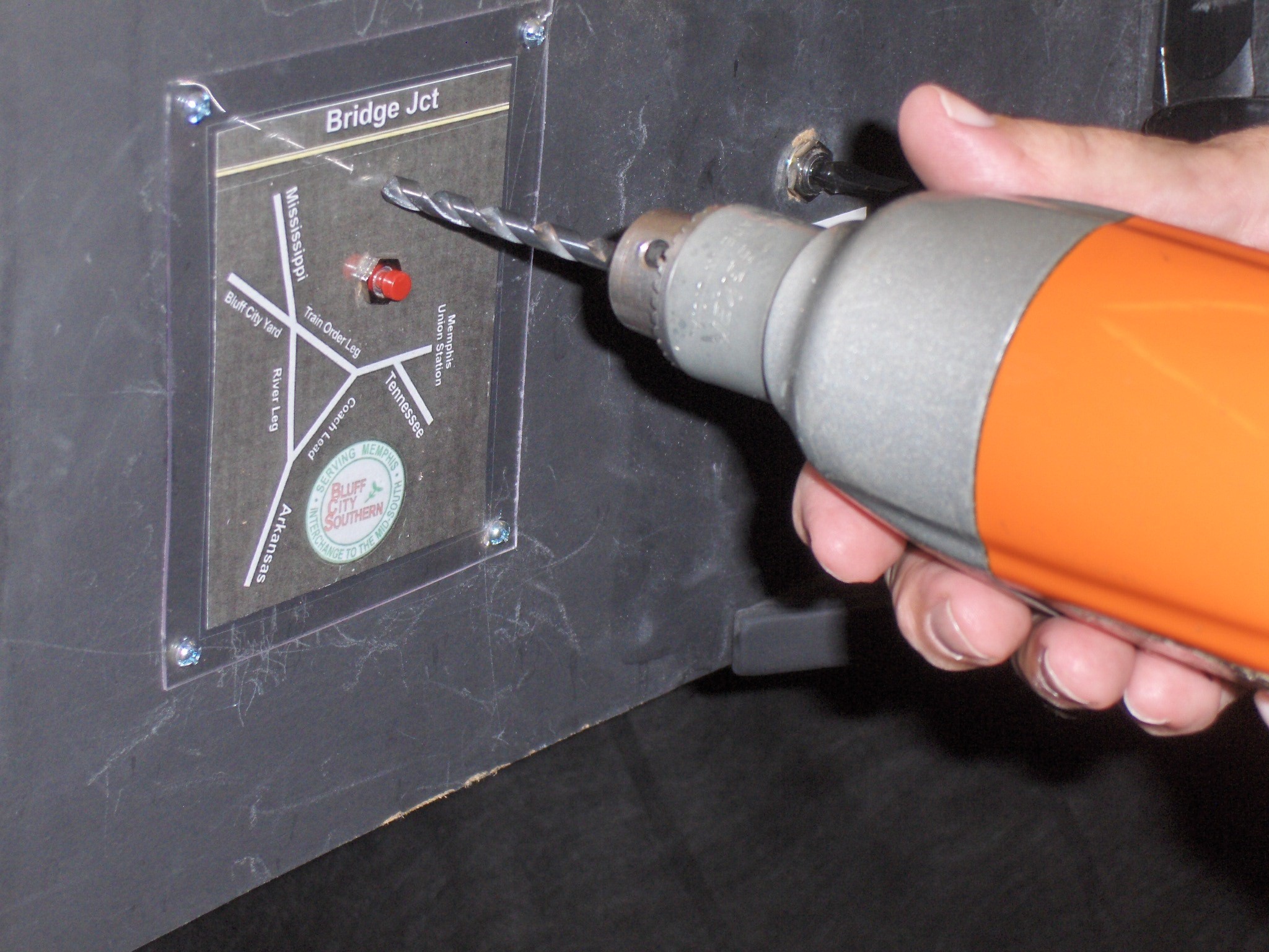
Kevin Kizer, a retired signal maintainer, starts to drill the pilot hole for the train order signal in front of the train order station at Bridge Junction on the Bluff City Southern. This small but long drill allows us to make sure there are no obstructions below the layout base before we drill the full size 3/8” hole.
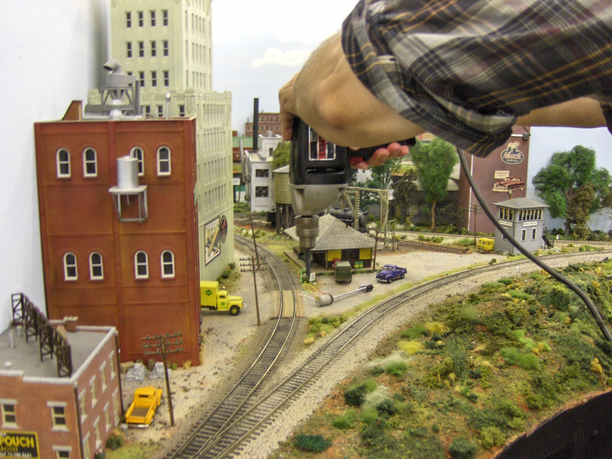
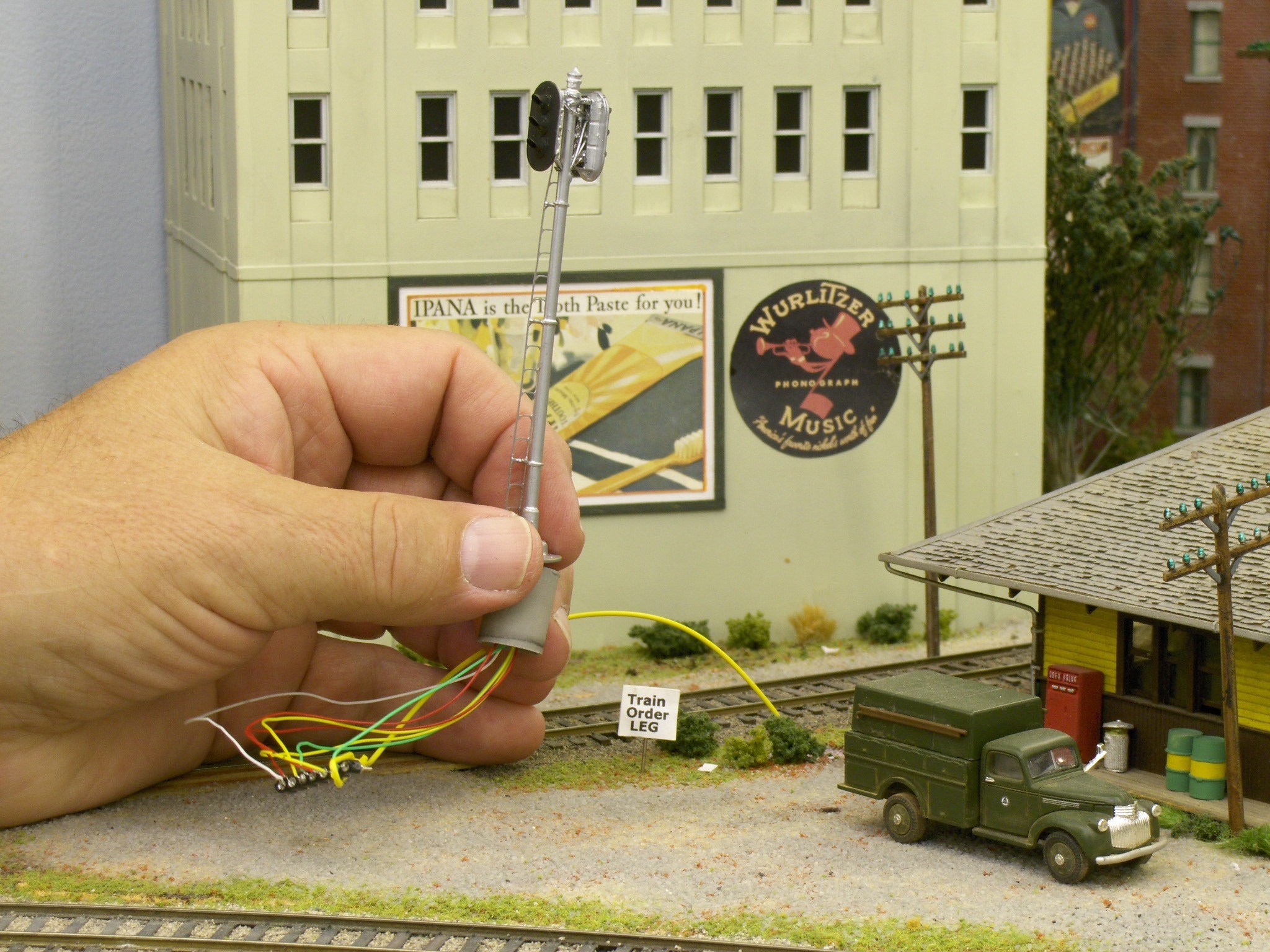
Now we drill the full mounting hole, so we can place the train order signal that comes pre-wired from Tomar Industries.
We’ve made a base out of Plastruct tubing so the signal sits a little higher and is free to be bumped but hopefully not broken. I painted it a nice concrete color.
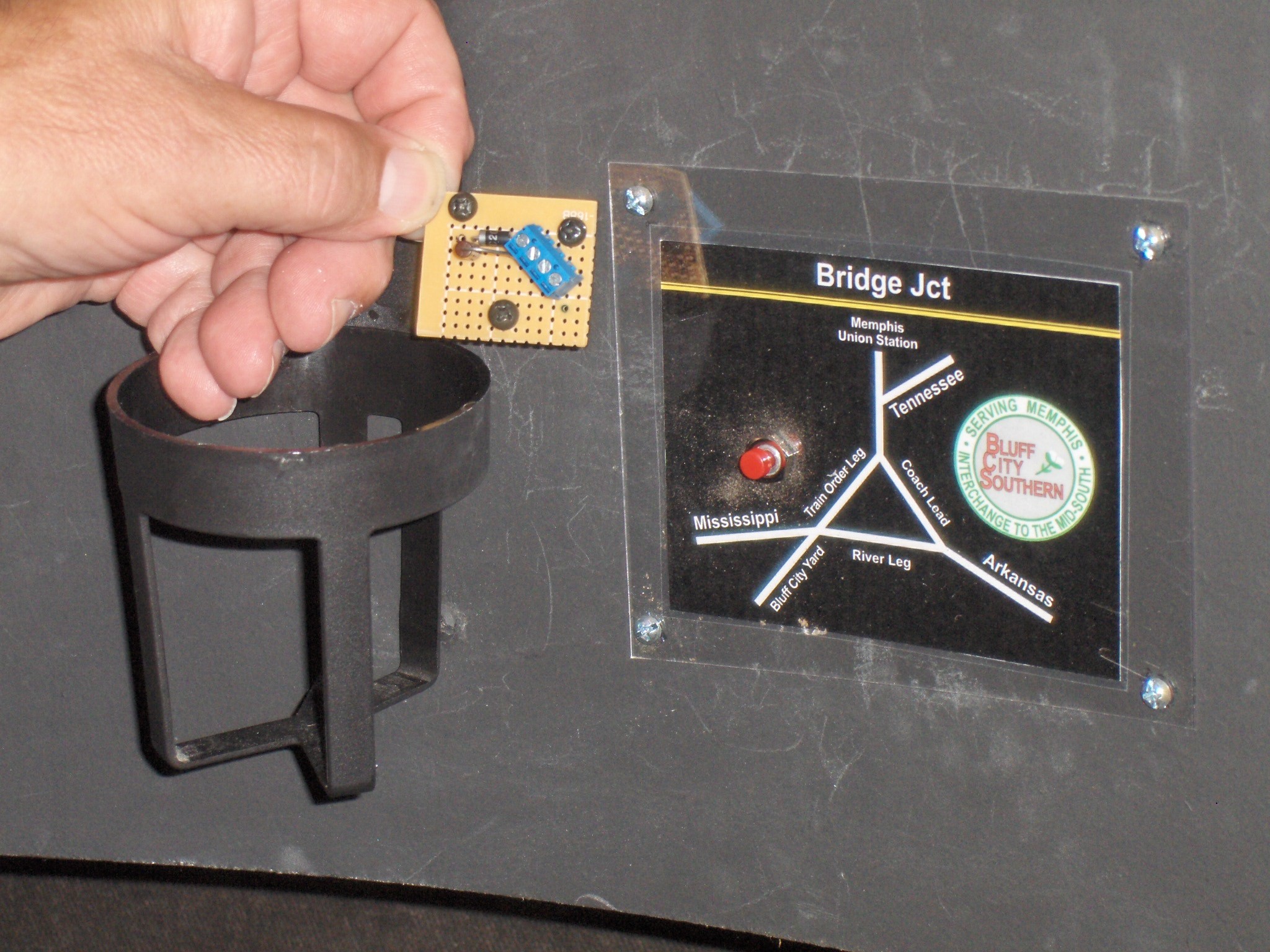
This is the signal mounting board that Kevin made to fit under the layout next to the signal, so we can connect the wires from the power supply to the signal itself. We will attach this to the layout base with hook and eye tape (aka Velcro).
First, we must mount the train order signal so engineers headed to the left and the right (i.e. from Bluff City yard and the Tennessee leg) can see the signal head. Even though this is a 3-light signal, we are only using the red and green lights.
Kevin is installing the signal mounting board. This signal will be controlled by two push buttons on the layout fascia. One is mounted at the exit of Bluff City yard and the other is mounted at the exit of the Tennessee peninsula.
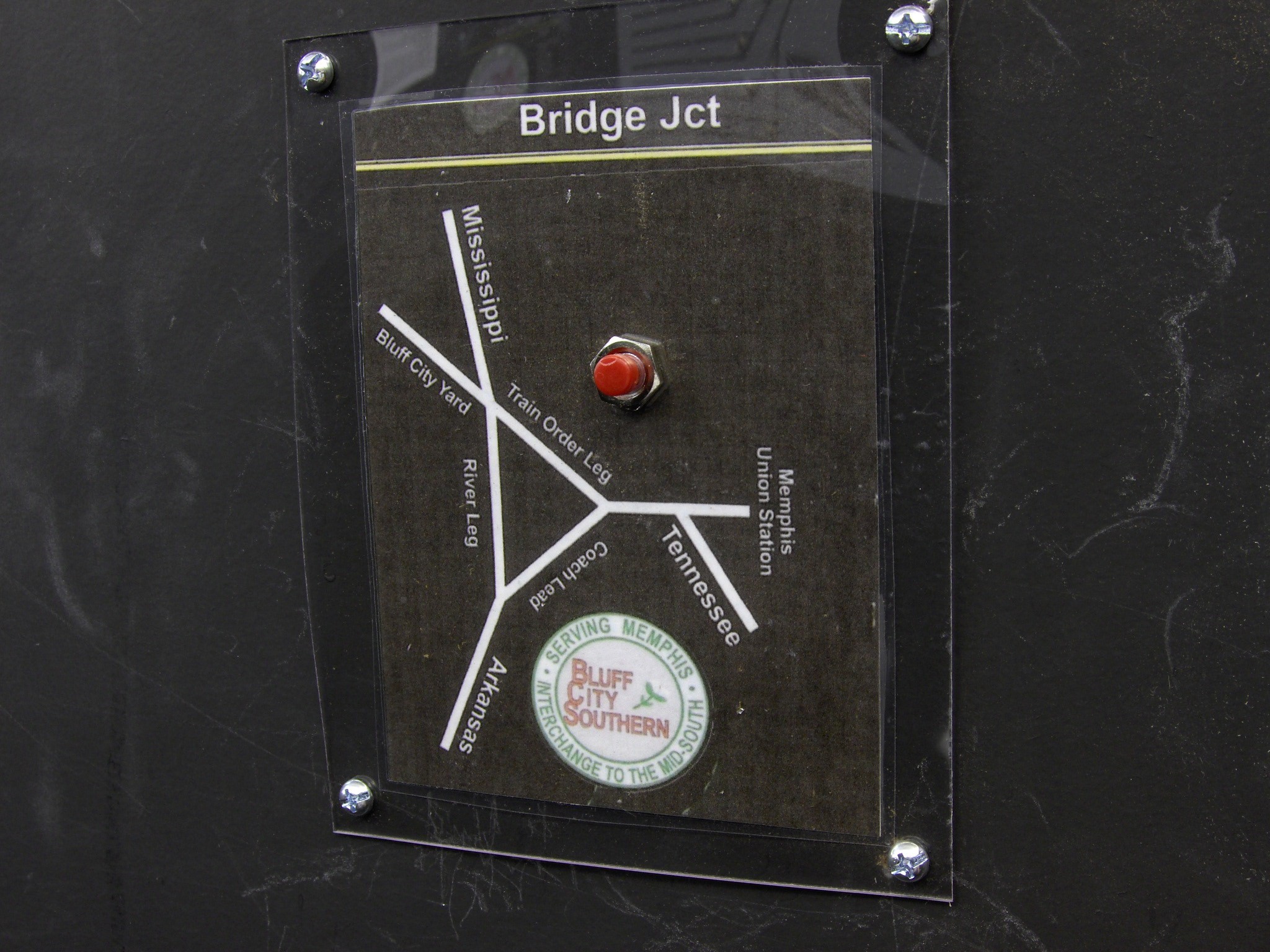
This is the placard at Bridge Junction next to Bluff City yard. We’ve already installed the push button that will control the signal.
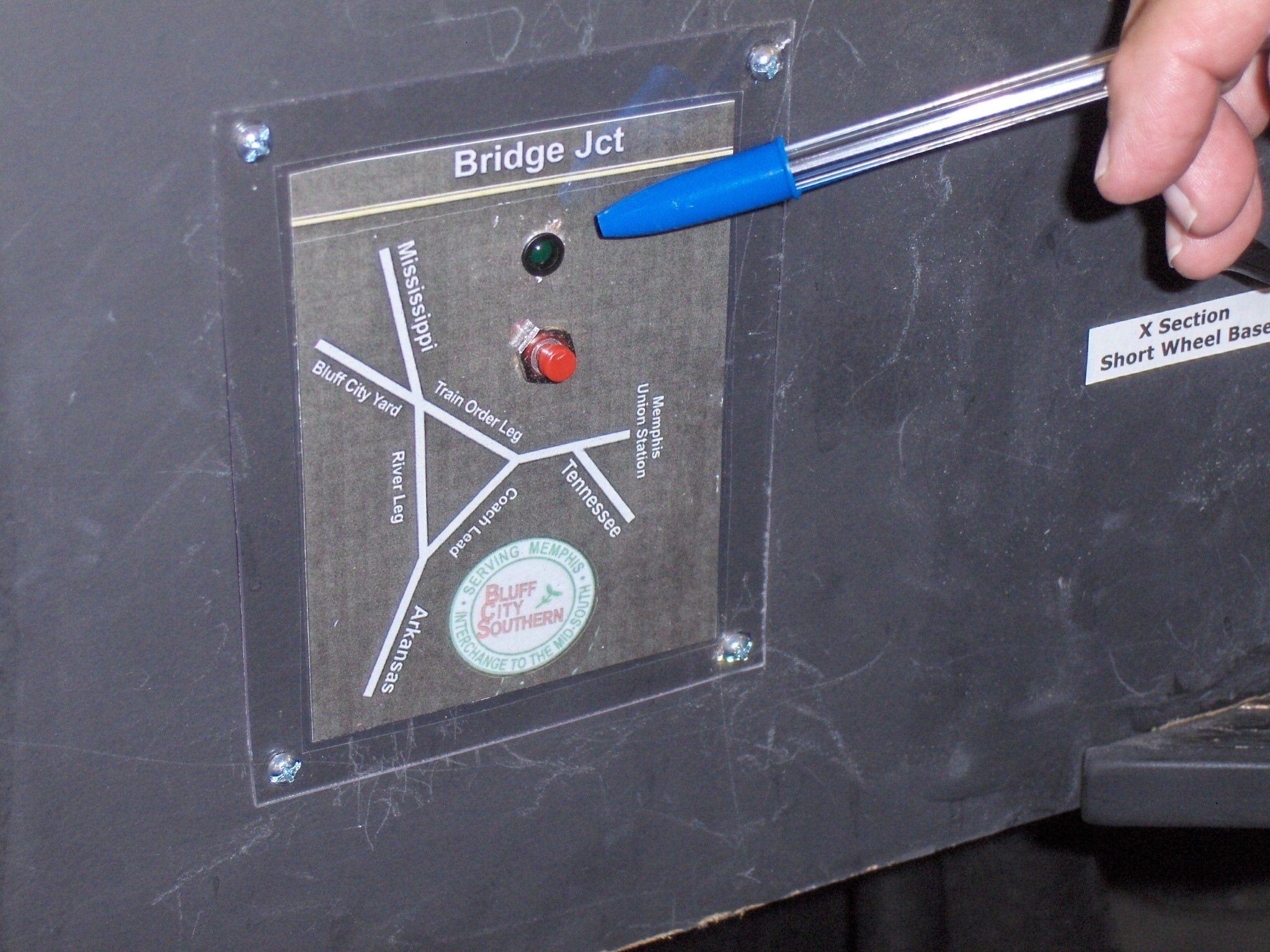
We’ve done the same thing on the other side of Bridge Jct. at the exit of the Tennessee peninsula.
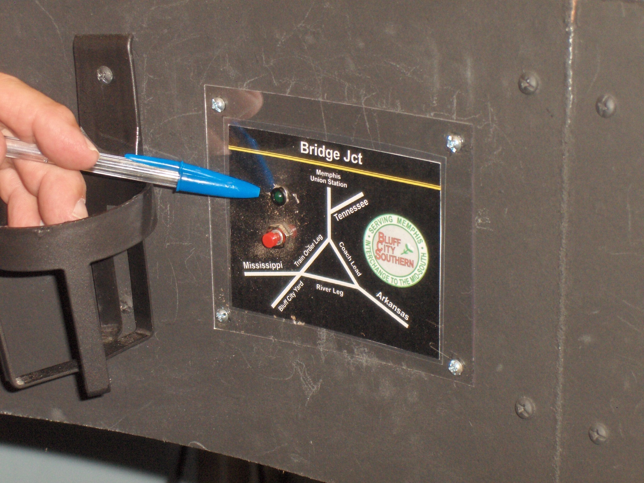
Next, we drill a hole for the green LED that will tell the engineers it’s safe to proceed through to the other side. The LED is just a repeater of the train order signal for the engineer. Normally this LED is dark i.e. not lighted until it receives a clear signal to turn green. The train order signal itself will always show red until the line is clear for a green light.
Here we’ve installed the green LED at Bridge Junction and we did the same thing on the other side at the Tennessee peninsula.
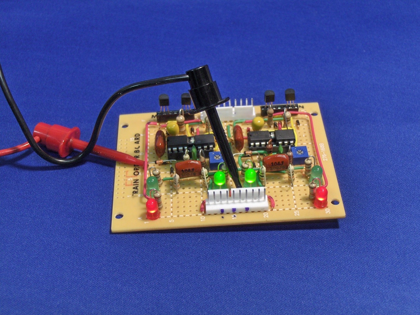
To make everything work Kevin designed this LED driver & timer board. In the back are the 4 transistors and in the front are the connections to the wires for power and for operating the signals. In the middle are the 4 black boxes that are the timer circuits one for each color in both directions….so 4 are needed. There are also dropping resistors to protect the 6 LEDs on the board.
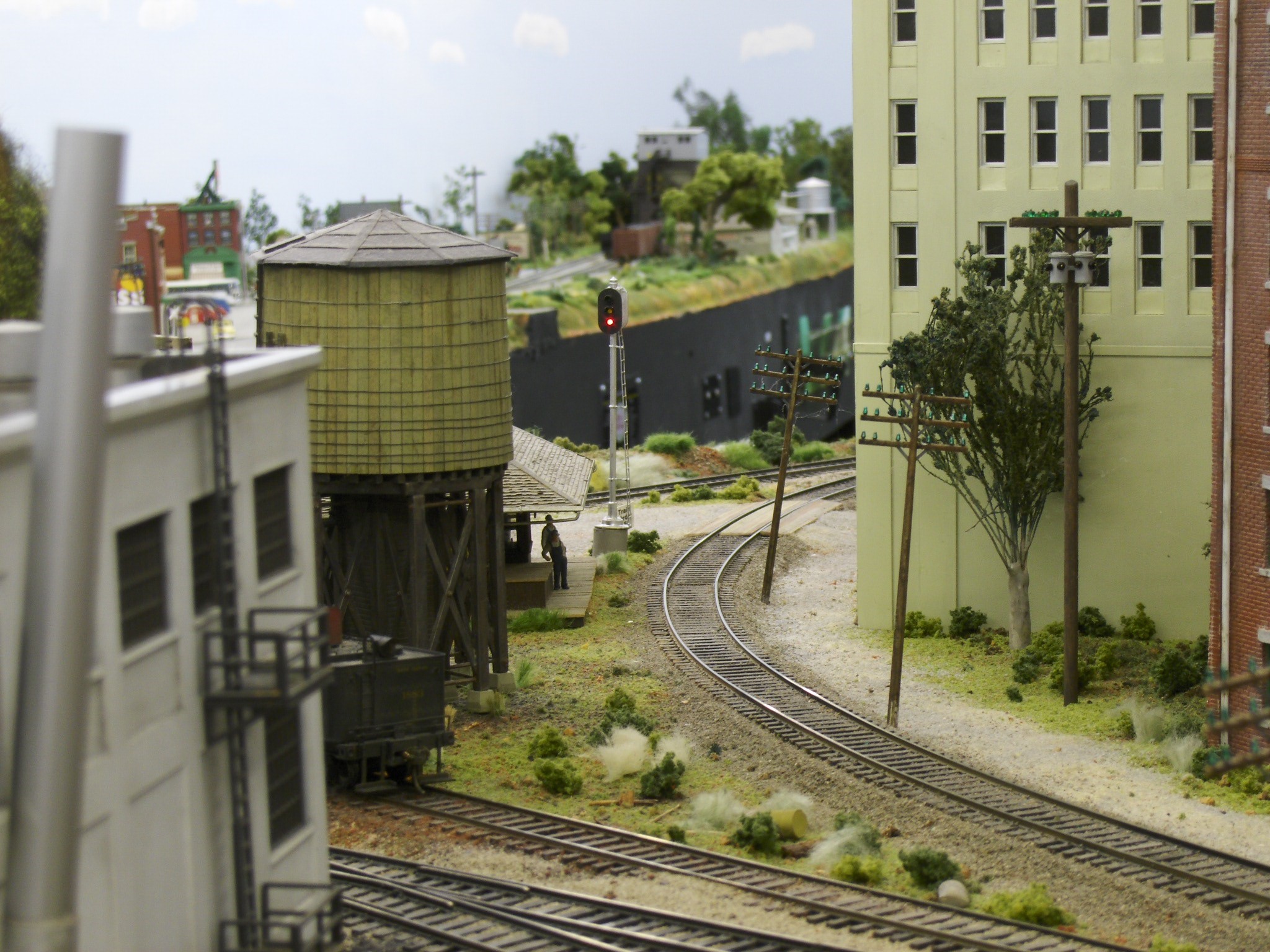
Here’s the view from the Tennessee peninsula. The train order signal is now red calling for all Mississippi bound traffic to stop. The signal is also red for traffic to Tennessee.
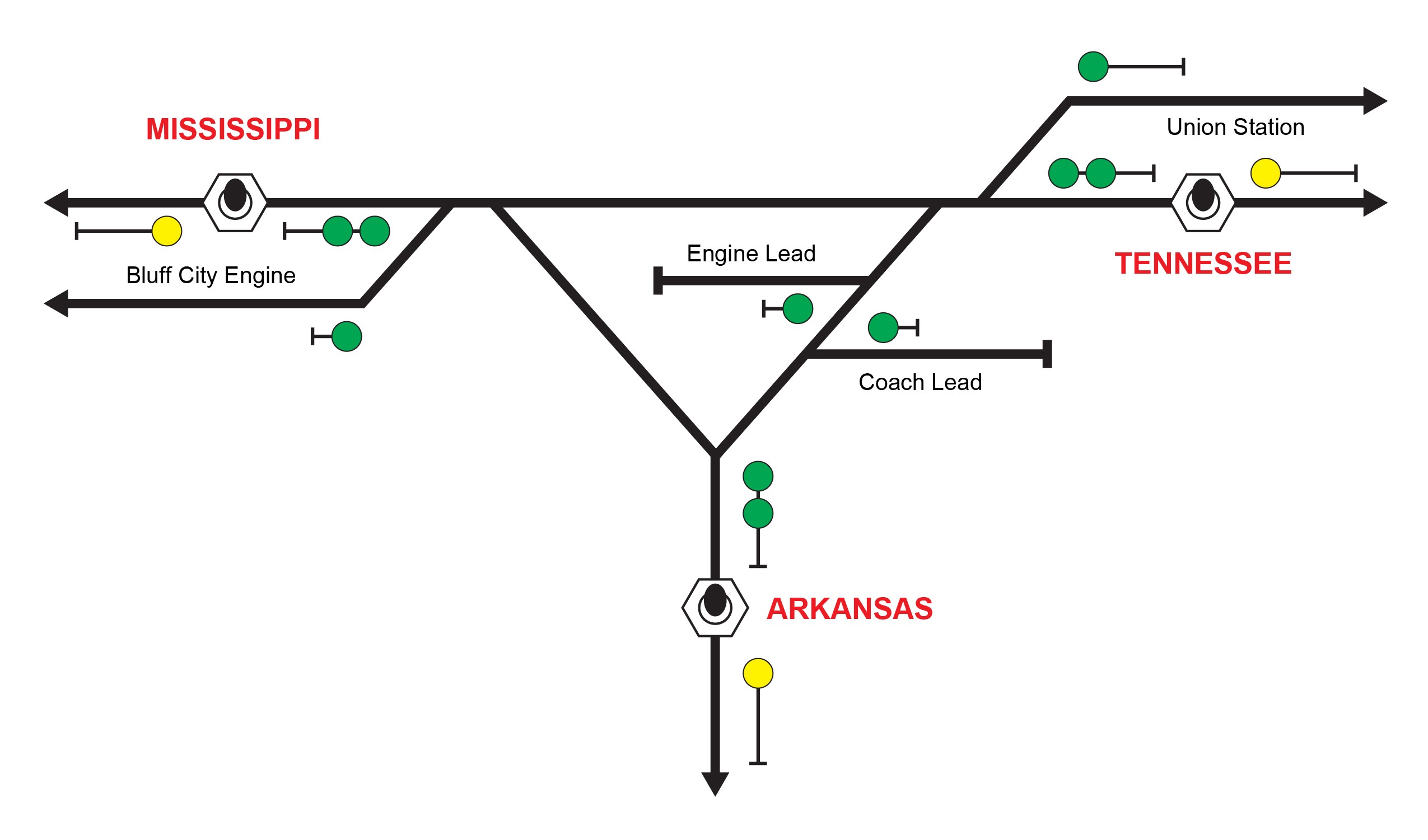
Here is a graphic showing how the layout is arranged. On the left is the Mississippi leg, on the right is the Tennessee leg and in the middle, is the Arkansas leg. Each leg is its own peninsula. The Arkansas leg is about 20 feet, so the engineer must walk about 40 feet to get to the other side to free his train from the train order operator.
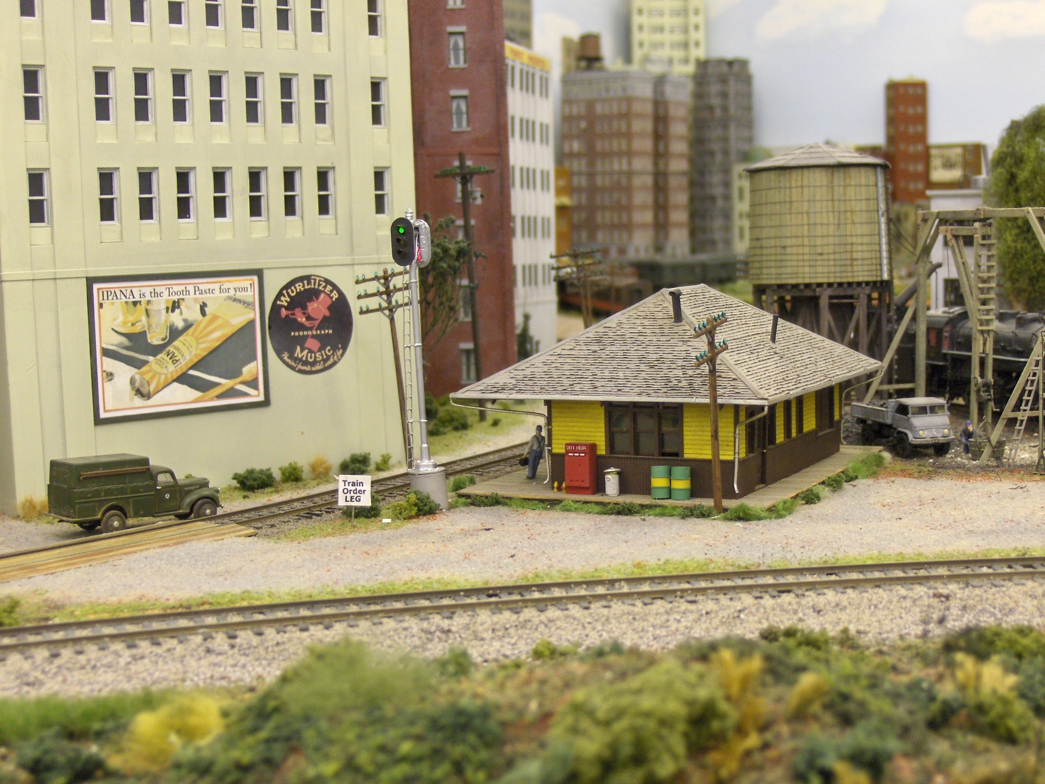
Here the train order signal shows green. That’s because the engineer has pushed the button at the Tennessee panel after walking around the Arkansas peninsula from the Mississippi side. Now he is free to head off to Tennessee. After 30 seconds the timer circuit will set the signal to red again.
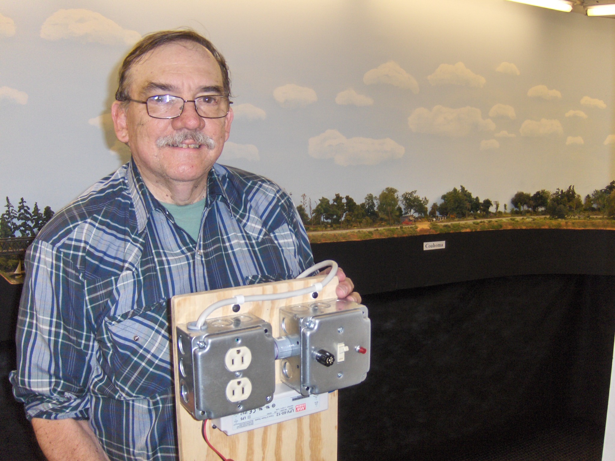
The final item is the power board. This contains 110-volt line into a work box with a duplex plug for a soldering iron. It also has a fused on and off switch in the work box on the right. Below is the 12-volt D.C. power supply that will operate the signals that we installed and will install. Next time we plan to get started on the home signals that protect Bridge Junction itself.
More in this series:
Installing Approach Signals for an Interlocking Plant: Part 1
Installing Approach Signals for an Interlocking Plant: Part 2
Have something to add to the story? Leave a comment or connect with us on Facebook.



Thanks for the article. While I understand real world signals and blocks, I've purchased books and watched videos but, am like a monkey solving a math problem when I start working on interlockings for my own board, until now. I finally started to get it in "Part 1". Thanks.
John....Just a great presentation, clear and to the point. Thank you!!
i have walthers scenemaster cantiliver grade signals with scenemaster crossing controler and detection cirticut controler and no instolation instructions.can you help
Great article. I use relays to change my lights as the train comes down the track. Odd enough I use the same color of wires as you do.
Nicely done, but for myself, I would have made the signals a little shorter in height. They look a little too tall. I really like the circuitry you built. How about sharing the circuit designs, parts list and where to purchase?
This has been seen for years. But what is the article or video called to proceed with the “home signals” ???
Are schematics for the several circuit boards available anywhere?
Keep up the good work.
Thanks for the information. Where do I find the information to buy the signals and the transistor circuit boards
This is a very nice series. I have some interlockings to install so I will enjoy following your progress.